How to edit audio at the level of individual samples?

I can’t get Ardour to zoom in far enough that I can manipulate individual samples. At maximum zoom-in, it’s possible that Ardour is displaying one pixel per sample, but there’s no easy way to tell how many samples are represented by each pixel in the waveform. Even if Ardour is showing each sample as one pixel, that’s not very useful: I can’t even distinguish individual pixels, let alone edit them. I expected to be able to zoom in to where each sample is displayed as its own dot and/or vertical line, clearly separated from the preceding and following samples.

Am I missing something, or is there really no way to do this?

Thank you,

– Ed

1 Like

Ardour doesn’t offer sample editing. It is a non-destructive audio editor.

If you want that, you need an audio file editor, where you can modify the sample values, or a DAW that allows this despite claiming to be non-destructive.

1 Like

I would also like this, having used an old (2005) version of Adobe Audition for nearly 2 decades, which (despite being microsuck only) was an excellent product, and sitll works perfectly in wine.

Here : https://www.audacityteam.org/

Let’s take a step back, why would you actually want to do that?

In the vast majority of cases changing values of individual samples of a bandwidth limited signal will not produce a result that one would expect. It’s not a connect the dots.

Inter-sample peaks the the prime example:


The red line (top and bottom) indicates the digital peak, corresponding to the sampled data (blue dots). and when playing this, the result is a perfect sine-wave (black line) exceeding the digital peak.

Even changing of of the blue dots slightly will produce overtones …

Most soundfile editors (incl. audacity) do not upsample, but just show you a connect-the-dots waveform display, not an actual oscilloscope display.

There may be a better way to accomplish what you intend.

2 Likes

Fascinating, can you explain more about this? ie. what voltage regulator or other (supposedly analog) component pushes the votage above or below what the individual samples say they’re supposed to be?

It’s a digital to analog converter. It’s job is to synthesize a waveform, not join the dots.

And note: there is only one correct waveform given the set of sample values, it’s not subject to circuitry design or anything else.

2 Likes

I can do better than that :slight_smile: There is amazing 20 min video on the subject, that should be mandatory watching for every audio engineer:

https://xiph.org/video/vid2.shtml

It not just explains sampling, but bit-depth and dithering as well.

9 Likes

Thanks, just watched it and it’s quite a fascinating video.

There are missing pieces in my knowledge/understanding of digital audio however. A transistor isn’t “smart” - it doesn’t realize that it’s processing an audio signal, and doesn’t choose to adhere to one conversion function or another. Every schematic i’ve seen of DAC/ADC’s are simply tools that convert a voltage to a bit field or vice-versa.

Yes, i understand that given a set of samples there maybe only a single set of sine waves that when added up, matches, all the math behind it etc… but at the simple hardware components, i fail to see where this or the whole timing/frequency component comes into play…unless there’s some inherent property of electricity itself that i don’t know about.

This is #2 of a 2 (or multi) part series, i’m off to watch part 1, then any other ones i can find… thanks again for the link!

The function of a DAC is to generate the analog waveform defined by the digital samples. You don’t need to understand how this is done to understand that this is its purpose, and that if it doesn’t do this, it is inherently flawed.

It is certainly possible to read up on the internals of DAC operations, but is really doesn’t seem very relevant to the topic at hand.

1 Like

There is usually a cut-off filter (high order low pass) before an ADC and after a DAC. That filter design is critical and some consider its design to be black magic

Also modern DAC are rather complex (internally oversampling to a few MHz)… but we’re getting off-topic.

PS. the first xiph video is about video codecs and not really relevant here. Also not nearly as good as the 2nd.

It’s impractical (and rather abstract) to explain at “the simple component level”. It’s a bit like asking how an individual spark plug knows about torque and rpm in a combustion engine.

The electronic components are assembled, as Paul said, to perform a function which converts digital signals to analogue in a predictable way, and the mathematics describes that way.

Bear in mind here that mathematics is, in part, a formal language which is used to to describe how things behave, whether that is an object falling or a pendulum swinging due to gravity, how torque is derived from an engine based on the characteristics of that engine and it’s inputs, or an electronic circuit’s behaviour.

In this case, the mathematical properties p[resented in Monty’s video, idescribe the characteristics of the D to A converters that are used by audio applications.

Why they exhibit these characteristics is, if you really.want to know, is something you will have to study for yourself.

Cheers,

Keith

1 Like

(Replying to my own post to provide more detail.)
In the past I’ve occasionally found a need to edit samples. But right now all I want to do is trim two audio clips at zero crossings, so I can join them without generating a click.

Yes, I know I could use fades, but I need to extend a note that doesn’t last long enough, and there’s no way to just generate a longer one to begin with.

Thanks for all the discussion!

– Ed

There are no zero crossings (that you can use for editing). This is a myth created early in the life of digital audio editing.

It has been discussed quite a few times here on the forums. I think someone did manage to push back on me to the point where I admitted it wasn’t an absolutely crazy concept. But it is still a myth.

Search the forums for zero crossing, you’ll find stuff. Meanwhile, use fades. If there’s silence rather than sound in one of the audio regions, the fade won’t matter; otherwise it will do the job.

[ EDIT: re-reading your goals … you can’t really do that, unless zero crossings actually existed. But they don’t. If you pick a suitable fade shape, you may find that the effect is not noticeable (I did this recently editing bits of my wife’s EP). ]

3 Likes

Exactly. I still can’t get it: a ADC measures voltage at every let’s say 48 thousandth of a second and accumulates the resulting bit values into a PCM waveform, and a DAC does the opposite: for each value in the waveform it sets its output voltage to the value described by the bits in that value, and maintains this voltage for the next 48 thousandth of a second, ie. until it’s time to fetch & output the next value.

Where in this process is there any question of solving for (or somehow accidentall stumbling upon) a sinewave or combination of sinewaves that matches the points specified in the waveform? What part of my understanding is wrong?

I don’t think any modern, mainstream DAC works like that. This may be useful in your research: Digital-to-analog converter - Wikipedia

But even if it did (and older audio DACs did do this) it’s done internally and isn’t what the entire DAC circuit outputs.

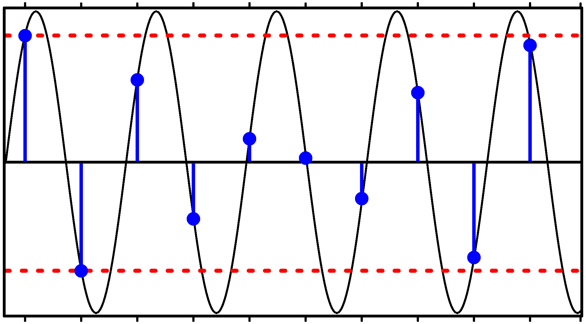
But if you believe the typical digital audio marketing BS, if you put a pure analogue sine-wave into an ADC and then pass that digital data into a DAC, the resulting output signal would not be a pure sine wave; it would have lots of “stair-steps”. The Xiph/Monty video demonstrates that is not true.

But what if the output signal did have those stair-steps? What would that sound like in reality?

To understand this, you need to perform something like a Fourier analysis on the signal, to see what frequencies such a signal would present.

You would then quickly realise why the digital audio marketing is BS and is, in fact, preying on people’s ignorance of how digital audio (and electronics in general) works.

@x42 gave a clue:

To revisit my previous analogy, your questions are akin to saying “I know that the spark plug receives a timed electrical pulse, but I don’t understand how this causes constant, smooth rotation instead of jumps”, because you haven’t studied how engines work.

To understand it fully, you probably need a year or two of study of electronics and the associated mathematics (e.g. Fourier, Nyquist, Shannon, etc.), and this is really not the right place to go into that.

I would suggest you have two rational choices:

  • Accept that this is how D-A converters work based on testimony from experts
  • Go and study electronics so you gain a deeper understanding of the subject

These are not mutually exclusive choices.

Edit: the following may be useful https://www.youtube.com/watch?v=pWjdWCePgvA

Cheers,

Keith

2 Likes

So, bottom line is that a DAC is much more complex than what people think…?

1 Like

Complexity is in the eye of the beholder. It certainly works differently than a naive understanding of the process might suggest …

1 Like

I’ve been an analog IC (chip) design engineer for more than 40 years. My take on the topic adds to @paul ‘s statement. In the digital-centric but still naturally analog world we live in, the concepts of so-called “data conversion” are intuitively clear to many. Certainly most Ardour users.

Having designed a few of these blocks along the way, though, I can assure you that the IC implementations - especially at the precision used in digital audio - are exquisitely complex.

5 Likes

This video is amazingly clear and concise.
It leave me with a question, though. Does that mean that a naive fade in or fade out done by ramping up or down the sample amplitude leads to noise/distortion ?