Yep, I read that too. I think he uses it just for live concert recording? He had a few issues with the bongs and seamless playback on the unit when he first started using it. All addressed now with the latest firmwire updates. I concur that he is certainly no slouch and reading about him using it definitely convinced me to buy. I think he uses a SADiE LRX2 system for the session recordings? Also nice to read he uses Audient preamps 
1 Like
This is a diagram from the patent that @bradhurley linked to.
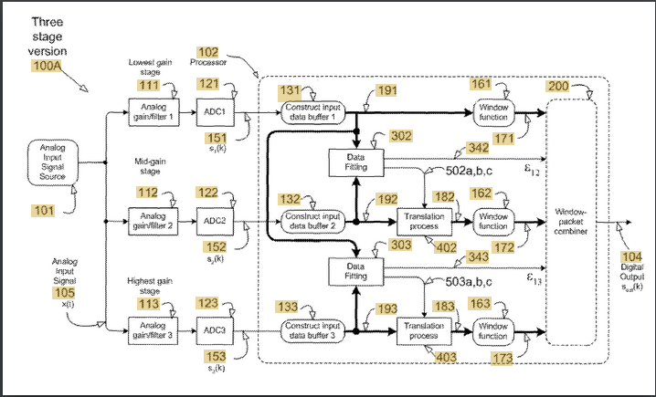
The filter will be an antialiasing filter with multiple selectable cutoffs, one for each sample rate. There is more going on here than a block diagram can show.
What can be seen is that the DSP is doing most of the work. Precision analogue electronics are expensive, so anything that can be done in DSP will be. The actual values of gain in each stage aren’t as important as the DSP knowing what those values are. The best way to do that would be for the DSP to measure the relative gains of each stage.
I saw that this setup can take a level of +12dBV without clipping. That’s 11.26 V peak to peak which is impressive from four AA batteries = 6V. (It is possible).
Wondering where +12dBV might come from I found that Shure have actually tested the maximum level an SM58 can put out and it’s +10dBV produced by a 1kHz source at 160dBSPL. For some context 140dBSPL is the threshold of pain, NASA estimate ten metres from the Space Shuttle launch is 180dBSPL, and at 194dBSPL the pressure of the peaks is twice atmospheric pressure and the troughs are a total vacuum. (i.e. the sonic boom from a jet fighter).
Capturing extreme sounds without clipping means a low gain. The lowest gain stage which deals with the extremely loud sounds could be a unity gain buffer.
1 Like
Exactly. For example box 101 the analog input does not say mic input, it could just as easily be the output of a preamp. For the gain/filter/ADC… where does one end and the next begin? Gain stage really means gain matching and most ADCs already have filtering as a part of their conversion some being analog and some being digital. It is important to remember that the patent drawing is designed to both protect the holder while at the same time make it as hard as possible for a company in a foreign country (that doesn’t recognize the patent) to copy. The names chosen for each block obscures what it does or at least how it works. It tries to look more complex than it is. Blocks 131, 132 and 133 may only be 1 sample in length for example. Blocks 402 and 403 may only add the exponent needed to correct gain. blocks 161, 162 and 163 are likely just a buffer. block 200 is a switch controlled by blocks 302 and 303 (compares data to a fixed value). The digital output is not the device output but rather the output of this one block. Note that this one block (102) says it is a processor so the functions inside it are firmware not actual units. Digital output (104) is then fed into another buffer of probably 8k samples (so 32bits wide = 32kbytes) but that is probably a part of the USB chip… or maybe the same processor as 102. Again the drawing is made to protect the holder, not provide an actual schematic. In this case it is the idea that is important more than the how.
You could be right here. I tend to place the priority of latency over almost everything else and most small CPUs (dedicated DSP chips are mostly integer math) are not so good at floating point multiplies. However, there are only two per sample and it would be easy to detect the difference in analog gain on the fly to compensate for changes for variation in temperature during use. There will be a part of every analog audio cycle where all three of the ADCs should be giving the same value with a gain compensation.
Remember that there is a preamp in front of this circuit. That pre may have a low gain to keep the p-p within the power supply or DC to DC converters are cheap and easy and so the internal PS may be higher than the batteries would indicate. Many condenser mics work only with 48V and I don’t know any that will work with less than 24V so they would have a converter for sure if they offer phantom power.
Anyway, great explanation. I hope I added to it rather than coming across as disagreeing.
1 Like