I’m disappointed. So a “buffer” which to my previous understanding simply meant a period of time to store data for processing now “has a gain of 1.0 while offering greater current”? If this be true, I’m clearly in over my head. Still got that brochure on lunar properties?
Roughly, yes.
12dB ≈ 3.98…
The formula is :
dB = 20*log10(gain)
so that only comes out as an integer when the gain is a power of 10. 20dB = 10, 40dB = 100
Turning the formula around gives :
gain = 10^(dB/20)
so for 12dB
gain = 10^(12/20) ≈ 3.98107170553…
an unwieldy decimal conveniently rounded to 4. 
There are buffers and buffers. In the digital world, a buffer is a storage area and generally causes delay, in the fire fighting world, a buffer is a bare area, in the woman’s monthly world we use the french word for the same thing… In the analog area (which we were talking about) a buffer is something that keeps an input from overloading an output in such a way that the output audio (or other signal) is not what is expected. So in this case a buffer is an amplifier that does not add or subtract gain but does allow the next part of the audio chain to draw more current. All amplifiers tend to do some buffering even if they also change the gain but they called a buffer if their function is to only provide a higher current output.
Brochure not needed, just send money 
So, just to be clear, in this instance we are not talking at all about a buffer as a period of time while the device figures out which bits to use? i.e. a delay in writing the audio to the SD card to allow for calculations?
In this case the gain is more important (voltage gain not power). We talk about dB gain because it makes more sense to our ears but in this case the actual gain is more important because the input number is is a 24bit int which we don’t want to manipulate. rather we want to hard set the exponent part of the float we create to give the gain we want. If that amount of gain is an odd amount, it doesn’t matter. It doesn’t even matter if the gain steps are not equal. The numbers just have to fit. I do not know my binary math well enough to give reasonable examples, I chose 4 as an example because it is an even binary number… but the exponent part of the float would be chosen not to be exactly a gain of 4 (unless it just happened to work out nice) but rather a value that allowed the significand to remain the same. In other words it is important for the gain steps to translate to “nice” numbers rather than easy for humans to read numbers. So after figuring out the gain, the closest whole number in dB would be stated… or perhaps the number that rolls off the tougue the best as is the case with engines (what size really is a Chev 350?).
A buffer is never a period of time even in the digital world though it may have the effect of creating a delay. In the digital world a buffer is a place to keep things until we are ready for them. A place in memory to put stuff if you like. The reason such a buffer is needed is that even if we were dealing with one sample at a time, there are two things accessing this buffer and we do not want (ever) both things to try to access this buffer at the same time. So in the case of audio, the ADC writes to a buffer some amount of samples (1 or more but normally at least 16). When it has finished writing to that buffer, it sends a signal to the computer (an “interrupt”) and the audio software in the computer then knows it is allowed to read that buffer and process the audio it holds.
And no, we are not talking about that kind of buffer. In this case I was talking about an analog buffer who’s job is to match one amplification stage to another. These are generally high impedance input and low impedance output (high current output) devices.
gain = 10^(12/20) ≈ 3.98107170553…
That is the voltage gain I posted. The formula to convert power gain in dB to a number is 10^(dB/10).
I am sorry, I did not mean to indicate you were wrong so much as make sure others reading knew what we were talking about. Or at least knew they are different.
Meanwhile, I’m having lots of fun with my Mixpre6 mark ii. Just recorded concert with the knobs all the way down just because. Glad to know we have the numbers covered
No need to apologise. I too only wanted to clarify.
When you’re taliking about ‘32 bit float’ are you referring to IEEE 754 with sign, exponent and fraction like this?
s|eeeeeeee|fffffffffffffffffffffff
That is put back together as +/-(1+fraction)*exponent. The exponent takes the value of 2^(e-127). The gain then would take power of 2 values … 1/8,1/4,1/2,1,2,4,8 …
If the exponent was to be used as a gain control it can only work in 6dB steps.
I may be missing something.
Nope you have it exactly right. Three ADCs. Use the 24 bit ADC value for the sign and fraction. The exponent would set the ADCs output to:
ADC1 would be either +6, +12 or +18 (it seems +12 is what is used)
ADC2 would be set to 0
ADC3 would be set to -6, -12 or -18 (it seems -12 is what is used)
This means the “gain stage” in front of each ADC needs to be precise. The ADC with +12 in the conversion needs to have a gain of exactly -12 and so on… well it would not (as you have already pointed out) be exactly 12 dB but rather the ADC conversion would be a gain of 4 and the gain stage would be a gain of 1/4. This is why I suspect that a pad is used for the “gain stage”. So:
Mic -> pre -> split -> (-24) -> ADC-24bit int -> (+24) 32bit float -> switch -> output
                |
                    -> (-12) -> ADC-24bit int -> (+12) 32bit float        ^
                |
                    ->  (0)  -> ADC-24bit int -> (direct) 32 bit float    ^
Not sure how my diagram will turn out… Anyway the switch selects between the three outputs from the bottom up. So long as the bottom ADC’s 24 bit value is between 1 and -1 that value is used, If the value is either 1 or -1 then the next up value is looked at and so long as it’s value is between 1 and -1 then it’s value is used but if it’s value is also 1 or -1 then the top ADC’s output is used. In my mind, the “gain stages” are all pads (well the bottom one has none) because they would then be simple resistive networks that tend to wander less with time. They are probably situated where the temperature is reasonably constant and at least one of the resistive components would be variable set at factory for exactly the right gain.
Loving the attempt at a diagram. I think it looks great It’s all beginning to make more sense in my head now. Thanks so much for the detailed analysis/hypothesis. So you would put good lunar currency on a single preamp splitting to three ADCs? In essence similar to the Zoom F8 allowing for simultaneous safety recording on other channels. The nice feature here being that the new devices automatically piece everything together.
The only question that remains (and it may be a big one): If Paul Isaacs claims that the uppermost input values are aligned so that they can never clip the preamp/adc, in my mind (presently unaffected by the lunar atmosphere) isn’t your idea of pads the opposite of what he is suggesting? Wouldn’t three preamps be more in line with this? As in, the preamp processing the upper values is calibrated to the clipping point and the other two have varying amounts of gain?
I’m no expert but isn’t padding a single preamp sonically inferior to using three preamps of varying gain? i.e. a single preamp (not working at its optimum through most of the range) vs 2 or 3 preamps all working at close to their optimum and combined in a clever way. There is definitely a disconnect in the way Paul is describing it on other forums but I do understand that some of this could be marketing and not wanting to let loose the true functionality (even with vague patent floating around).
In this case we are switching from one signal to another on a sample by sample basis. This means all three gain stages must sound exactly the same. That is each semi conductor, each capacitor, each wire length and each resistance must be exactly the same… except the bits that change the gain. The thing is, if you change something to change the gain, you must also change various capacitors that the gain change bits interact with to maintain the same sound. This is so far as I can tell starting to step into impossible land. In theory, it should be possible to use an amp with a different gain as a gain stage but in practice this would give artifacts that differ for various parts of the waveform. My training is in Broadcast Electronics (not engineering) from back when analog circuits did everything. So what I am saying is based on that. There has to be some kind of single preamp or buffer that provides the mic with a uniform load. So there is already a single amp of some kind. I would expect a full mic preamp that provides a level suitable for the ADCs for a uniform sound at all levels. providing a preamp that can stand the highest output of any condenser mic is probably not that hard as the amp in the mic will likely clip first even next to the canon or jet engine. I don’t think such a company can afford to have a “this mic pre sounds weird” comment due to unmatched preamps. I do not think pads go against anything this person says… and I would also point out that he is talking to many people who want to understand what is going on without a specific this is the component used to do it. Headroom in almost all cases means having a power rail high enough for those peaks. It is the low level sounds that are hard to capture without adding noise. I still vote for a single preamp. I still vote for the “gain stages” being a simple pad with very careful layout to minimize lead capacitance and inductance. I am simply looking at things from the “if I was going to build this, I would…” point of view. I certainly don’t claim I have it exactly right, their engineers may feel that with micro circuitry active gain stages are easier to use. Thats fine too… these are quite far out of both my buy-able range and my usage type anyway and so they are not something I am likely ever to be in the market for. I would rather spend the extra money on more channels. This unit is great for location recording where the number of inputs is not a large. Think movie location recording, stereo recording of a concert using a stereo pair or MS recording, voice over or even studio use where only one instrument is ever recorded at a time. I have 6 inputs (8 preamps) and though I rarely more than 2 inputs at a time… there are those rare occasions
OK, I think I get it now (famous last words). It is a clever design (while side-stepping Zoom’s own 2-stage patent) but it is beginning to sound far more like a prosumer marketing ploy versus something genuinely ground-breaking. I understand the use for a location recording with no chance for a sound check. Indeed, last night’s concert turned out just fine. But would using it in 32-bit float mode for a classical album session be any worse in quality than going for 24-bit and having to set the traditional gain knobs (oh, the inconvenience of it all!)?
If it is built right, the quality of the recording should not suffer at all and should be able to have a better dynamic range. Setting one’s levels for visible peaks right up to 0 rather than -18 means that while invisible peaks up to +20 are still rendered correctly, the main audio still has 24bits of resolution. The one thing to watch for is how is the audio recorded? One would want to make sure the recorded file retains 32bit float for storage and of course when printing to final media the resolution will be back to 16 to 24 bits so the peaks will either have to be limited or the whole recording have it’s level reduced to account for those peaks.
I would hesitate to call this unit prosumer as such. I think in the film (video?) industry this kind of box could easily be a goto for audio recording. I have not thought about the live orchestral recording before, but it could be very useful there too for overall micing even in a case where there are numerous spot mics used. To me prosumer means pretending to be pro but of lesser quality and I do not get the idea these are of less quality than any other box but rather that they seem to go extreme. I can not see a studio populating their setup with these as their main converters though. A studio has the advantage of “dialing in” the work space to known mics, converters and working levels over time.
Fair enough. I see them in the same way as I view the Scarlett/Clarett range from Focusrite versus their ISA standalone preamps. Both good at what they do but clearly one is more “pro” than the other. I realize that SoundDevices is catering mainly to video folk but nobody is going to mistake the quality of build or preamp of a Scorpio, 888 or 833 with a MixPre. Plenty good enough for my classical location needs but I hardly expect the Harmonia Mundis and Deccas of this world to be reaching for a MixPre or a Scarlett/Clarett interface. I would define “prosumer” more from the point of view of the user versus the quality of equipment. i.e. equipment with professional features but marketed for the amateur or lesser Gods of the recording industry.
It’s worth noting, though, that Tony Faulkner uses a MixPre 10T these days for at least some of his work, and he’s no slouch: http://greenroomproductions.biz/?cat=6
Yep, I read that too. I think he uses it just for live concert recording? He had a few issues with the bongs and seamless playback on the unit when he first started using it. All addressed now with the latest firmwire updates. I concur that he is certainly no slouch and reading about him using it definitely convinced me to buy. I think he uses a SADiE LRX2 system for the session recordings? Also nice to read he uses Audient preamps
1 Like
This is a diagram from the patent that @bradhurley linked to.
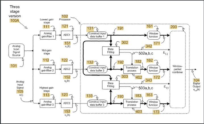
The filter will be an antialiasing filter with multiple selectable cutoffs, one for each sample rate. There is more going on here than a block diagram can show.
What can be seen is that the DSP is doing most of the work. Precision analogue electronics are expensive, so anything that can be done in DSP will be. The actual values of gain in each stage aren’t as important as the DSP knowing what those values are. The best way to do that would be for the DSP to measure the relative gains of each stage.
I saw that this setup can take a level of +12dBV without clipping. That’s 11.26 V peak to peak which is impressive from four AA batteries = 6V. (It is possible).
Wondering where +12dBV might come from I found that Shure have actually tested the maximum level an SM58 can put out and it’s +10dBV produced by a 1kHz source at 160dBSPL. For some context 140dBSPL is the threshold of pain, NASA estimate ten metres from the Space Shuttle launch is 180dBSPL, and at 194dBSPL the pressure of the peaks is twice atmospheric pressure and the troughs are a total vacuum. (i.e. the sonic boom from a jet fighter).
Capturing extreme sounds without clipping means a low gain. The lowest gain stage which deals with the extremely loud sounds could be a unity gain buffer.
1 Like
Exactly. For example box 101 the analog input does not say mic input, it could just as easily be the output of a preamp. For the gain/filter/ADC… where does one end and the next begin? Gain stage really means gain matching and most ADCs already have filtering as a part of their conversion some being analog and some being digital. It is important to remember that the patent drawing is designed to both protect the holder while at the same time make it as hard as possible for a company in a foreign country (that doesn’t recognize the patent) to copy. The names chosen for each block obscures what it does or at least how it works. It tries to look more complex than it is. Blocks 131, 132 and 133 may only be 1 sample in length for example. Blocks 402 and 403 may only add the exponent needed to correct gain. blocks 161, 162 and 163 are likely just a buffer. block 200 is a switch controlled by blocks 302 and 303 (compares data to a fixed value). The digital output is not the device output but rather the output of this one block. Note that this one block (102) says it is a processor so the functions inside it are firmware not actual units. Digital output (104) is then fed into another buffer of probably 8k samples (so 32bits wide = 32kbytes) but that is probably a part of the USB chip… or maybe the same processor as 102. Again the drawing is made to protect the holder, not provide an actual schematic. In this case it is the idea that is important more than the how.
You could be right here. I tend to place the priority of latency over almost everything else and most small CPUs (dedicated DSP chips are mostly integer math) are not so good at floating point multiplies. However, there are only two per sample and it would be easy to detect the difference in analog gain on the fly to compensate for changes for variation in temperature during use. There will be a part of every analog audio cycle where all three of the ADCs should be giving the same value with a gain compensation.
Remember that there is a preamp in front of this circuit. That pre may have a low gain to keep the p-p within the power supply or DC to DC converters are cheap and easy and so the internal PS may be higher than the batteries would indicate. Many condenser mics work only with 48V and I don’t know any that will work with less than 24V so they would have a converter for sure if they offer phantom power.
Anyway, great explanation. I hope I added to it rather than coming across as disagreeing.
1 Like